1. Compared with the old model, the new model has optimized the circuit structure, making the power supply work more stable. At the same time, it has added input reverse connection protection (using 150A MOS for reverse connection protection) and input low battery (low voltage) protection, and the low battery protection voltage can be adjusted from 9-50V to adapt to various batteries. When using batteries for power supply, you don't need to worry about damaging the power module and battery when the battery is low.
2. Power Description: Since the input current of this power supply is 20A, the output power is related to the input voltage. The higher the input voltage, the greater the power. For example, the input power of 12V*20A is 240W. The input power of 24V*20A is 480W. At this time, the power is 12V. Due to the limited heat dissipation area, please add a 12V fan for heat dissipation when the input voltage exceeds 10A or the output current reaches 10.
Module parameters:
1. Module model: SZ-BT07CCCV-A
2. Module name: 1200 W boost constant current module
3. Module nature: non-isolated boost module (BOOST)
4. Input voltage: DC 10-60V (direct input 10-60V without jumper cap to select voltage) (Updated on 2016/5/15)
5. Input current: 20A (MAX) If it exceeds 15A, please add a fan for cooling (with fan cooling, the input current can reach 25A when the input voltage is 12-24V)
6. Static operating current: 15mA (When the output voltage is increased from 12V to 20V, the higher the output voltage, the higher the static current will be)
7. Output voltage: 12-80V continuously adjustable
8. Output current: 18 A MAX. If it exceeds 10A, please increase heat dissipation (related to the input and output voltage difference. The greater the voltage difference, the smaller the output current)
9. Constant current range: 0.5-18A (+/-0.3A)
10. Input reverse connection protection: Yes (150A power MOS reverse connection protection)
11. Low battery protection: Yes (9-50V adjustable)
12. Working temperature: -40 ~+85 degrees (please strengthen heat dissipation when the ambient temperature is too high)
13. Operating frequency: 150KHz
14. Conversion efficiency: 92% -97% (efficiency is related to input and output voltage, current, and pressure difference. The smaller the pressure difference, the higher the efficiency)
15. Input overcurrent protection: Yes (when input exceeds 25A, it will automatically protect the power supply and will not boost the voltage)
16. Short circuit protection: Yes (input 30A fuse) double short circuit protection, safer to use.
17. Input reverse connection protection: Yes (150A power MOS tube anti-reverse connection. Can be reversed for a long time )
18. Installation method: 4 3mm copper columns
19. Wiring method: Terminal block (please use high current pure copper wire)
20. Output power: = input voltage * 20A, such as: input 12V * 20A = 240W The power when input 12V is 240W
21. Input voltage*20A For example: input 24V*20A=480W, that is: when input 24V, the power is 480W
- Note: The power is 240W when the input is 12V, 480W when the input is 24V, and 720W when the input is 36V
Features
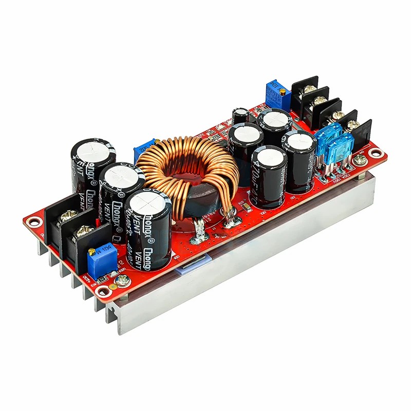
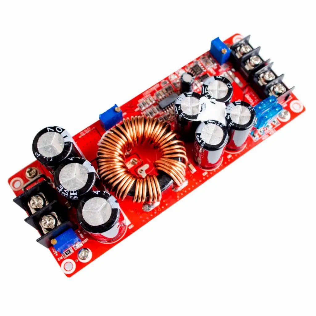
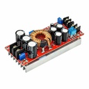
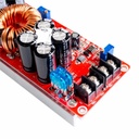
1. The power supply is made of powerful materials.
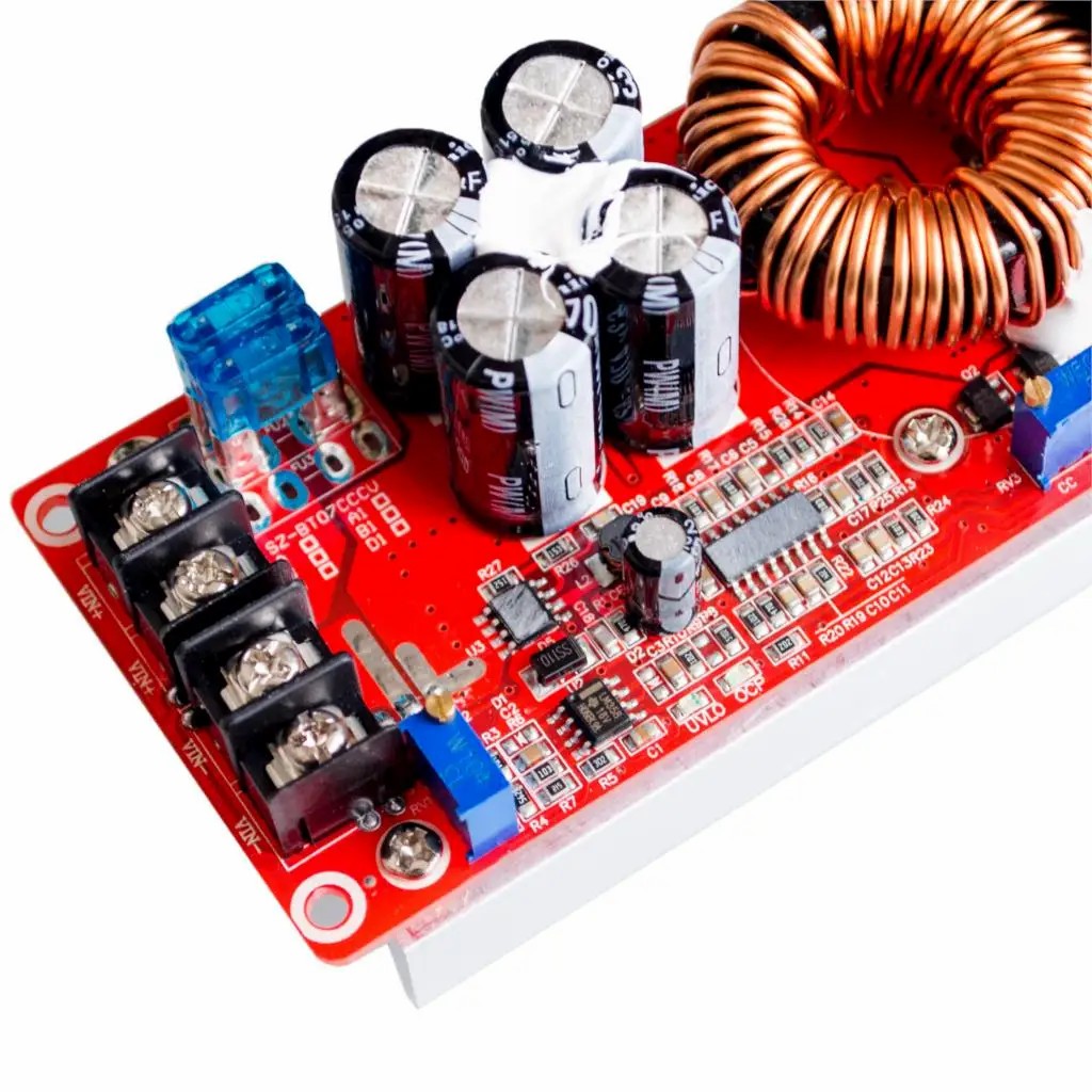
2. The input uses 4 63V/470UF high-frequency low-resistance electrolytic capacitors, and the output uses 3 100V/470UF electrolytic capacitors.
3. The 33MM ultra-high-power iron silicon aluminum magnetic ring is wound with 3 1.2MM pure copper wires to prevent over-temperature magnetic saturation under high current conditions.
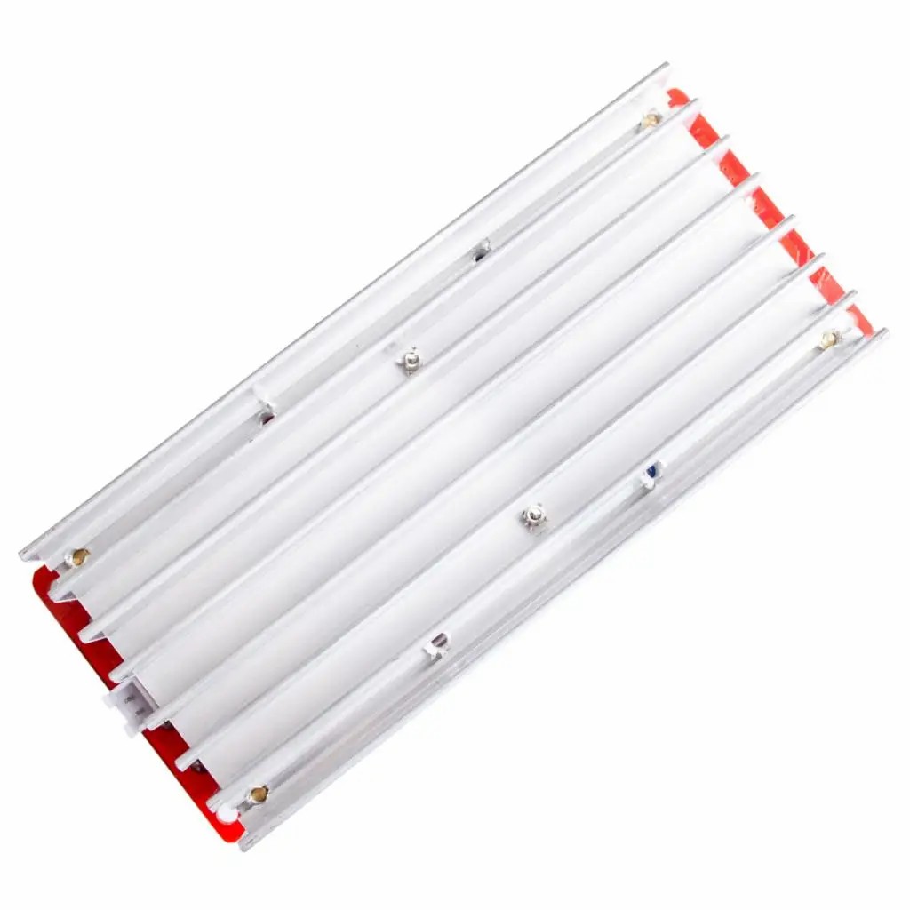
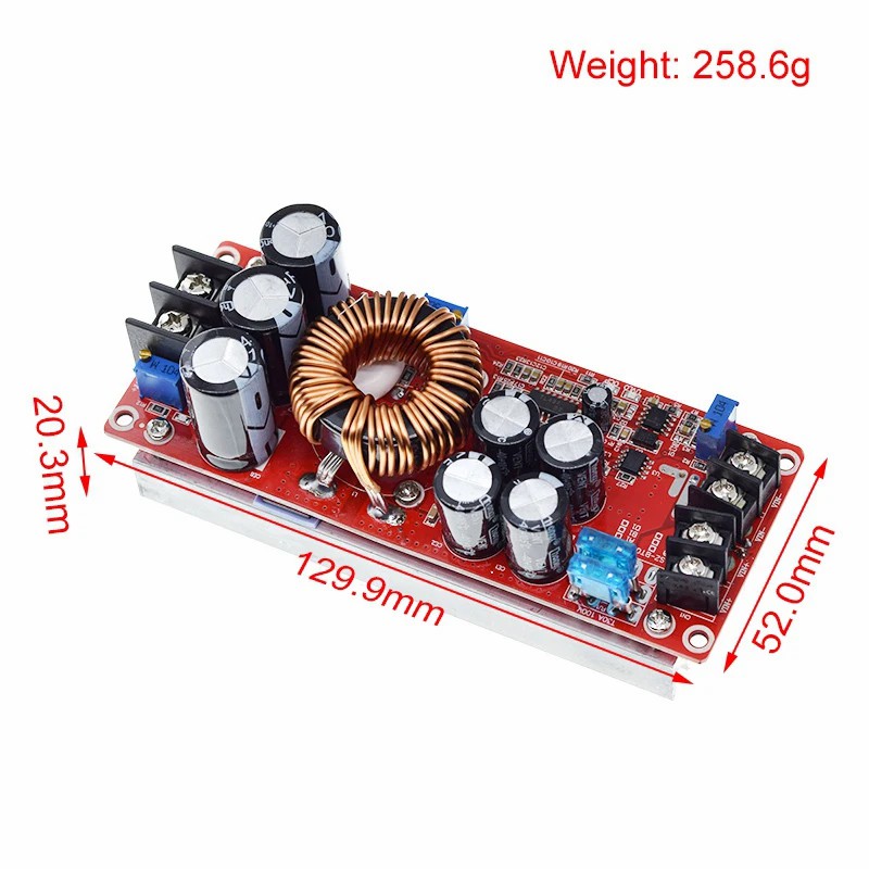
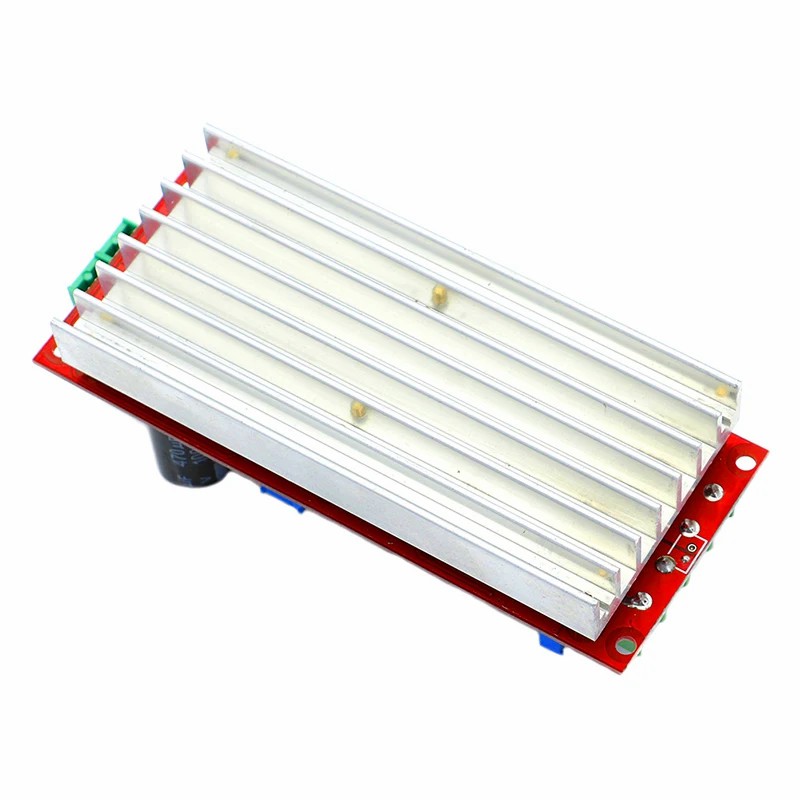
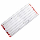
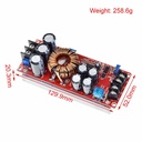
4. A 116MM*58MM*14MM aluminum radiator is used for heat dissipation.
5. The heat sink has a 5015 fan (5MM*5MM*15MM) installation hole; the imported power management chip output voltage and current are continuously adjustable.
6. Output voltage/output current regulation/input low battery protection regulation
7. Voltage adjustment: When the power is turned on and there is no load, use a flat-blade screwdriver to adjust the output end "V-ADJ" potentiometer (marked in the figure above) clockwise to increase, counterclockwise to decrease). Due to the large output capacitor capacity, the output voltage will react slowly when adjusted from high to low voltage. Jianyi adjusts the amplitude to a smaller extent. The default output voltage is adjusted to 19V for shipment.
8. Current adjustment: Turn the "A-ADJ" potentiometer counterclockwise and adjust to 3A before shipment.
Special note:
1. Never use short-circuit output to adjust the current. The circuit structure of the boost module cannot be adjusted by short-circuit.
2. Input low battery protection adjustment: Low battery protection is mainly used to prevent over-discharge of the battery when the input power is a battery, and the battery voltage is too low to damage the power module and battery. For example, set the 12V battery to low battery protection.
3. Connect a 10V voltage to the input end of the power module and use a flat-blade screwdriver to adjust RV1 (clockwise to increase the protection voltage value, counterclockwise to decrease the protection voltage) until the UVLO light is on. At this time, the low battery protection voltage is 10V. When the battery voltage drops to 10V, the power module does not rise (the input voltage is equal to the output voltage)
The following points should be noted when using a boost power supply:
1. The voltage of the input power supply must be above 10V.
2. When using a switching power supply as the input power supply, first connect the input power supply and adjust the voltage under no-load conditions. Then connect the load. (Make sure the switching power supply is always working), or first, adjust the voltage under no-load conditions, then disconnect the switching power supply, and then connect the load. Connect the switching power supply and the power module when the switching power supply is turned on. (Because the switching power supply has a climbing time when it is turned on. When the voltage is lower than 10V, the chip has not worked yet. It is easy to break down the MOS tube.
3. When using the constant current mode to set the voltage, the set voltage must be higher than the input voltage. (For example, if the input voltage of the power supply is 12V and the no-load output voltage is 15V, then connect a 3.2V LED lamp. This situation is not allowed. At least 4 LED lamps in series must be connected.)
Applications:
1. DIY a voltage-stabilized power supply with 12V input and adjustable output of 12-80V.
2. Power your electronic devices and set the output value according to your system voltage.
3. As a car power supply, it can power your laptop, PDA, or various digital products.
4. DIY a high-power laptop mobile power supply: equipped with a large-capacity 12V lithium battery pack, your laptop can be powered wherever you go.
5. Solar panel voltage stabilization.
6. Charge storage batteries, lithium batteries, etc.
7. Drive high-power LED lights.
Package Include
1 * DC converter