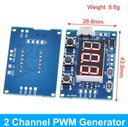
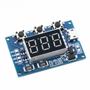
Description
Module highlights:
● 1. Two independent PWM outputs, which can be set separately for frequency and duty cycle;
● 2. Wide frequency range and high accuracy;
● 3. Capable of serial communication
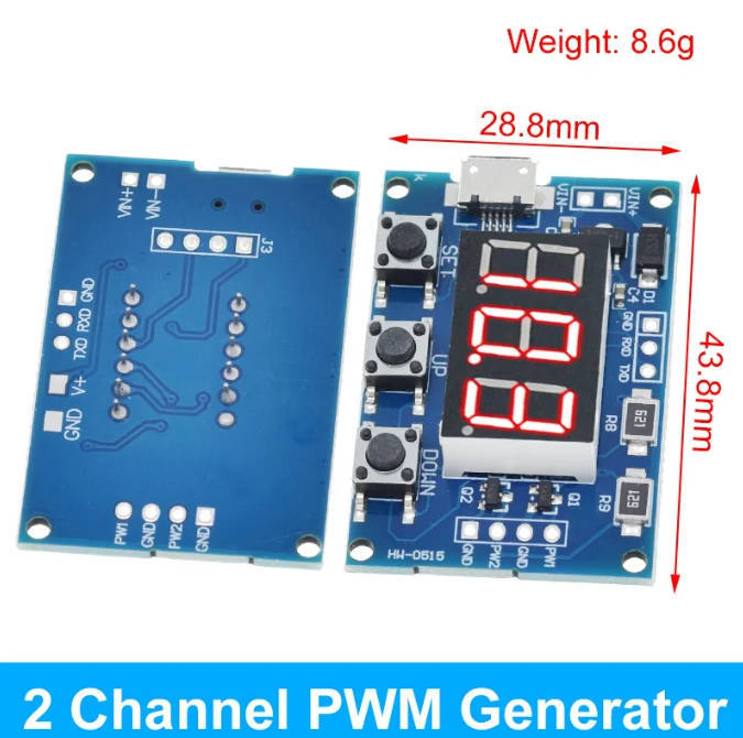
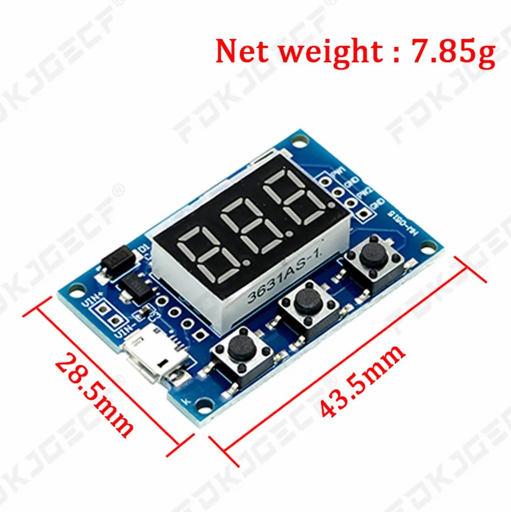
● Boundary dimension: 41 * 28mm Thickness: 1.6mm
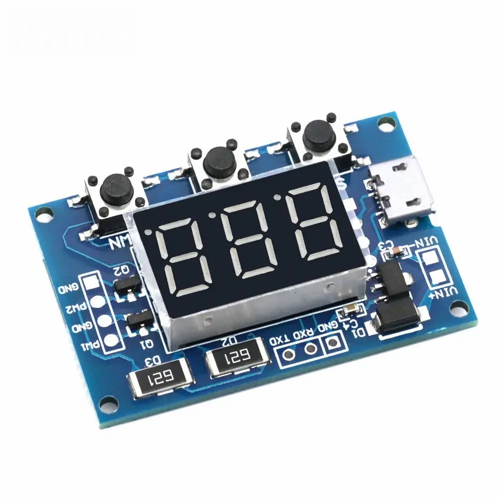
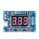
1, Module Description
Two independent PWM outputs can be set separately for frequency and duty cycle;
The frequency is divided into three ranges:
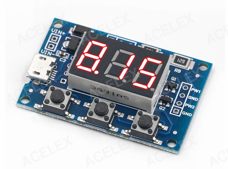
● 1. XXX (without Decimal separator): the small unit is 1Hz, and the value range is 1Hz~999Hz;
● 2. XX. X (the Decimal separator is in the tenth place): the small unit is 0.1Khz; Value range: 0.1KHz~99.9KHz
● 3. X.X.X. (three digits have Decimal separator): the small unit is 1 Khz; Value range: 1KHz~150KHz
● e. G. Frequency display: 100 represents PWM output of 100Hz pulses;
● 54.1 represents a pulse with PWM output of 54.1KHz;
● 1.2.4. Represents a pulse with PWM output of 124KHz
● Duty cycle value range: 0-100;
● Three frequency ranges share a common duty cycle, all set parameters are saved after power failure.
2, Parameter settings
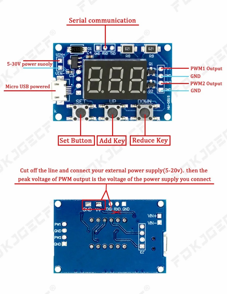
● The module has three buttons: Set, Up, and Down;
● 1. By briefly pressing the [Set] key, switch to display four parameter values (FR1: frequency of PWM1; dU1: duty cycle of PWM1; FR2: frequency of PWM2; dU2: duty cycle of PWM2). Before switching, there will be a corresponding parameter name flashing prompt.
● 2. Directly press the [Up] and [Down] keys to modify the current parameter value (long press can quickly increase or decrease).
● 3. There are three preset frequency values for each of the two PWM channels. On the frequency display interface, by long pressing the [SET] button to switch, the duty cycle of the three frequencies is consistent. (XXX: range 1Hz~999Hz; XX. X: range 0.1Khz~99.9Khz; X.X.X.: range 1Khz~150Khz).
3, Module parameters:
● 1. Working voltage: 5-30V supports micro USB 5.0V power supply;
● 2. Frequency range: 1Hz~150KHz;
● 3. Frequency accuracy: The accuracy in each range is about 2%;
● 4. Signal load capacity: The output current can be around 8-30 ma;
● 5. Output amplitude: default 5V V-pp (can be changed through external power supply);
● 6. Environmental temperature: -30~+70 ℃.
4, Applicable scope:
● 1. Used as a square wave signal generator to generate square wave signals for experimental development;
● 2. Used to generate square wave signals that drive stepper motor drivers;
● 3. Generate adjustable pulses for MCU use;
● 4. Generate adjustable pulses and control related circuits (such as PWM dimming speed control applications).
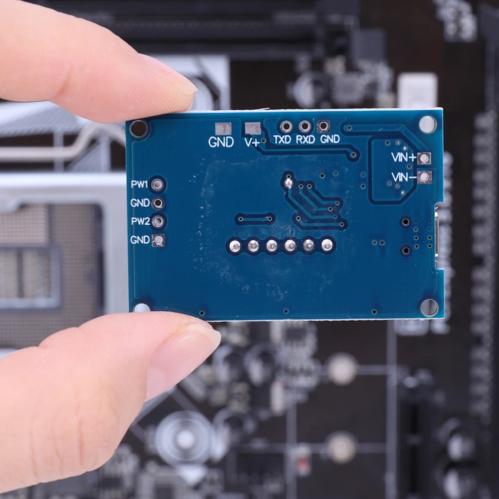
5, Serial port control
● Communication standard: 9600 bps
● Data bit: 8
● Stop bit: 1
● Check digit: none
● Flow control: none
● 1. Set the frequency of PWM
● S1FXXXX ": Set the frequency of PWM1 to XXX HZ (001-999)
● S1FXX. XT ": Set the frequency of PWM1 to XX. X KHZ (00.1~99.9)
● S1F: X.X.X.T. ": Set the frequency of PWM1 to XXX KHZ (0.0.1.~15.0.)
● 'S1': PWM1
● 'S2': PWM2
● 'F': Frequency
● 'D': Duty cycle
● 'T' is the end flag bit
● 2. Set the duty cycle of PWM
● S1DXXXT: Set the duty cycle of PWM1 to XXX; (001-100)
● S2DXXXT: Set the duty cycle of PWM2 to XXX; (001-100)
● Set successfully and return: DOWN;
● Setting failed and returned: FALL.
Package Include
● 1 * PWM module